
Full Circuit Design
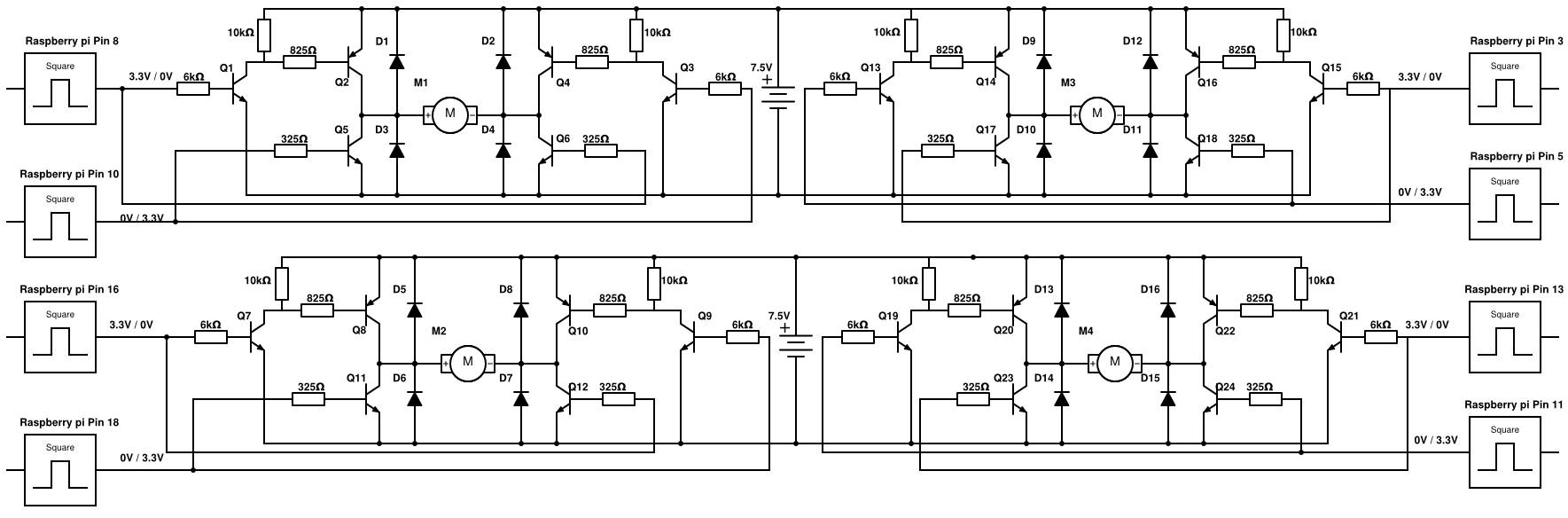
The ciruit design is based on H-bridge. All motors have an identical circuit.
Take the front left motor for example. When the wheel must turn forwards, Pin 8 will be at 3.3V, and Pin 10 at 0V. This causes Q1, Q2 and Q6 to go into saturation mode, and all others will be off. This induces a voltage across the motor, which draws up to 0.16A of current and turns the wheel runs. The diodes protect the motor by providing a current path for when one set of transistors is switched off and the others are switched on.
The resistor values were initially determined to be R1 = 6kΩ, R2 = 10kΩ, R3 = 825Ω, R4 = R5 = 325Ω. These calculations can be found in the Appendix.
When tested, it was found that the circuit could run the motor at 0.16A.The wheels were found to be spinning at 7 revolutions per second, corresponding to a horizontal velocity of ~143cm/s, or ~4.7feet/s. Hence, it is able to keep up with a normal walking pace.
This circuit was built on two breadboards with the power rails connected. This allowed one breadboard to be placed on each side of the robot’s chassis, which would minimise the length of wires from the circuit to the motors, minimising the noise and interference between wires.