Control Algorithm
P.I (Proportional And Integral) Control
As mentioned in the design and operation section, the micro-controller actually implements a PI control system. This consists of 2 terms, these are
the proportional and the integral values. Each part has the task of performing different calculations on something called an error signal, this is the difference between the required value and the
current value. In this case the error signal is how much faster or slower the generator is from the required 60Hz frequency.
The two operations are summarised below:
-
Proportional Control
This term is part of the total response, it is a basic proportional scaling system. Once the error signal (current frequency - target frequency) has been calculated, the proportional part of the program performs a simple scaling operation. The error is taken and is multiplied by a constant 'Kp' in order to get a numerical value which represents how large the power dissipation must be in order to reach the target frequency. Therefore the greater the error there is in the frequency, the more of the heating elements the micro-controller will have to turn on.
At the moment it may be difficult to find the exact value of 'Kp' to be used since it depends mostly on the generator properties, therefore this is constant needs to be set once this product has been installed in the Apayao province. -
Integral Control
This term is added onto the proportional control term in order to give our total system response. Once again the same error signal is used as above, but this time the error is integrated and then multiplied a constant 'Ki'. This integration process means that all previous errors are summed together hence the past history of errors is also considered here. This part of control system is mainly used to improve the accuracy in terms of the required power dissipation. After including this term into the control system, even a small change in the error signal will cause quite a sudden and steep response. This means that if we want to dissipate a certain amount of power, we can in fact reach this level much faster with the integral control.
Just like the proportional controller, we cannot theoretically predict what this exact value is going to be like because it depends mainly on the generator. So fine-tuning will be required by the engineers at the Apayao province in order to get this part functioning.
Flow Chart Analysis
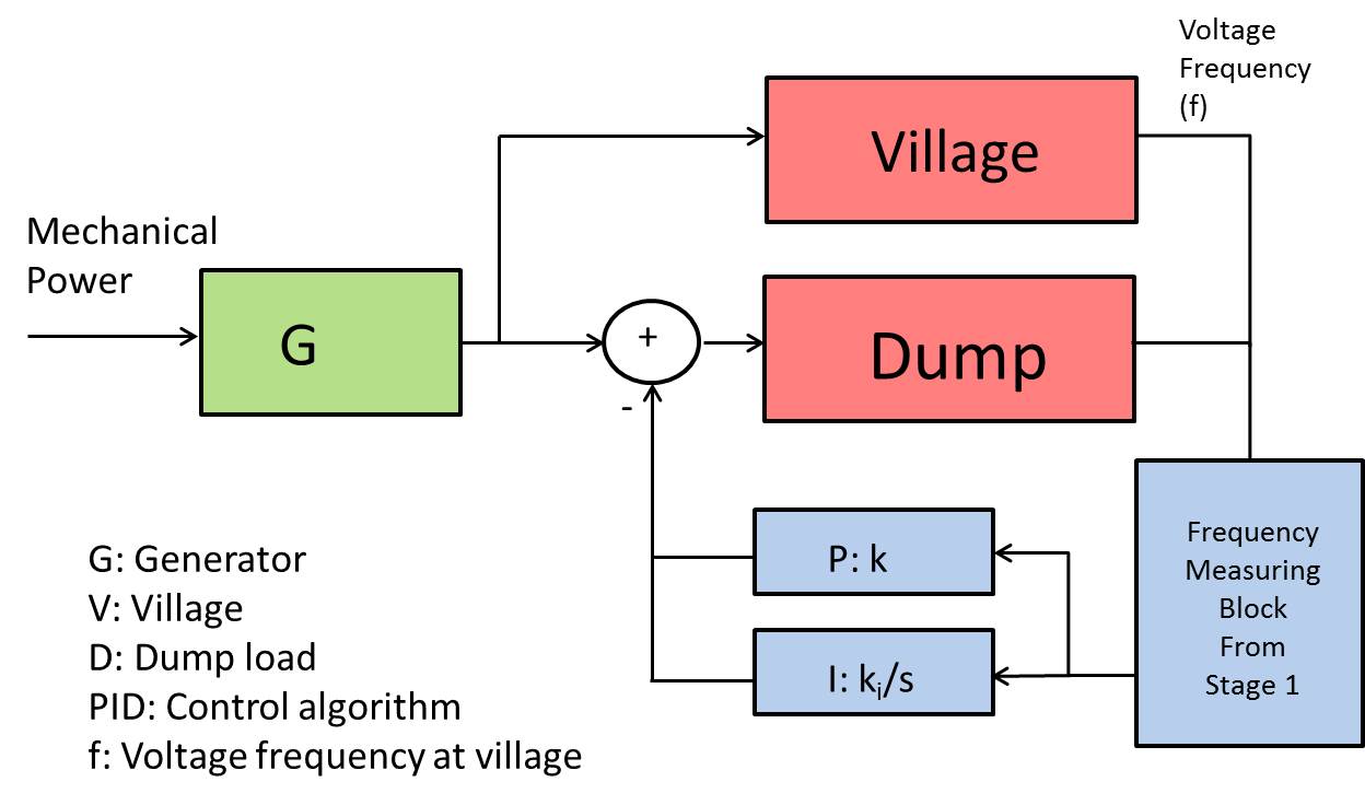
Figure 8: Control Loop For The Micro-Controller
Figure 8 shows a the control loop that is implemented by our micro-controller. The mechanical power is due to the micro hydro-power plant and this is the input to the generator.
The village and the load dump are the areas where the power consumption will be and the PI block is the control system (as described above) which will help regulate frequency.
The frequency of the generator is read in by using the circuit in stage 1, the block for this is included in Fig 8. The micro-controller then calculates the error value by simply subtracting the target frequency from
the obtained frequency reading.
This error is then fed into the PI control system (also shown), this then carries out the operations as described above. The final task carried out by the micro-controller
is to alter the power dissipation in the load dump. Then after this stage the micro-controller goes back to reading the frequency and the whole process is repeated.
In order view the full code, please read the relevant section of the report. This gives the C/C++ code which was used to configure the Arduino micro-controller, as well as a detailed explanation of its operation.